

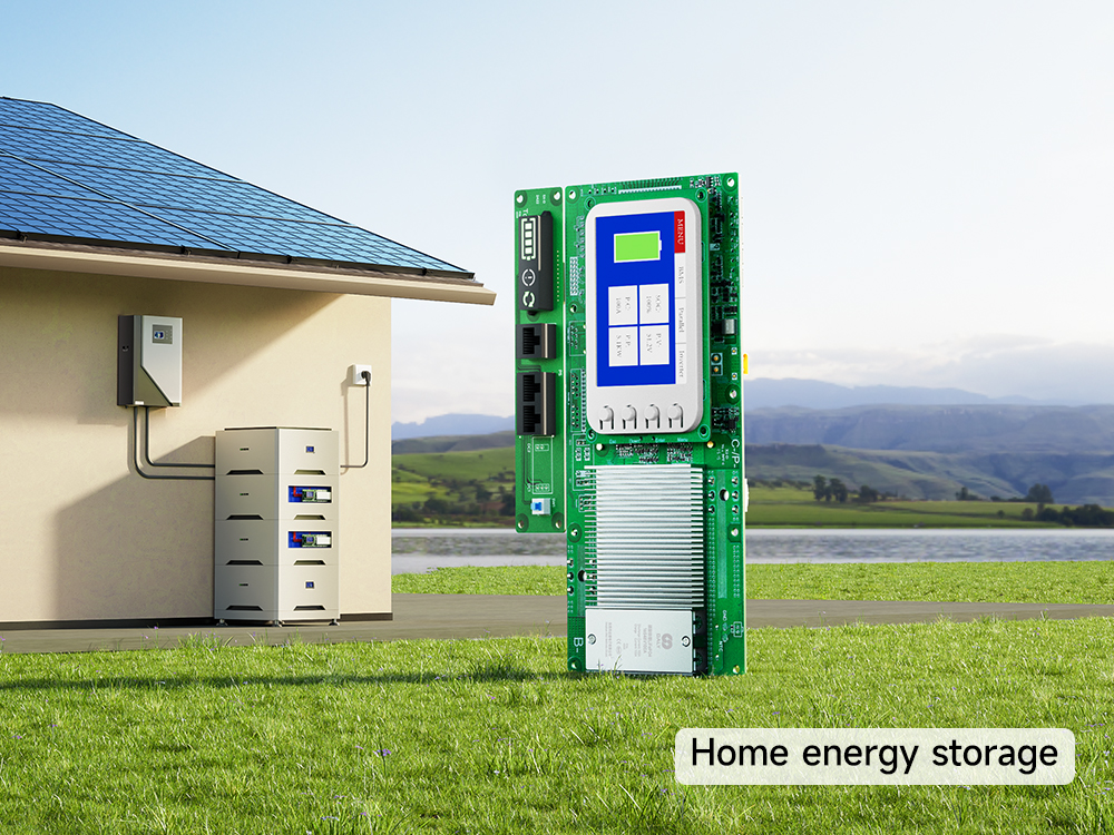
Choosing a battery management system (BMS) for a 48V-class LiFePO4 home storage pack starts with the battery design—not a product name. The key checks are the number of cells in series, discharge and charge current, inverter communication, temperature conditions, and any plan to connect packs in parallel.
This guide helps battery pack manufacturers and energy storage integrators prepare those requirements and identify which DALY home-storage BMS options warrant further technical review.
“16S” means 16 cells or cell groups connected in series. Using a typical LiFePO4 nominal cell voltage of 3.2V, the pack nominal voltage is 16 × 3.2V = 51.2V. Such packs are commonly described as 48V-class systems; “48V” alone does not identify the series count.
Confirm cell chemistry, series count, cell manufacturer voltage limits, and the battery operating voltage range before selecting a BMS. A generic DALY 16S wiring tutorial is available for understanding series-cell sensing, but it is not a substitute for the wiring diagram supplied with the exact LK or LM model.
Estimate battery-side discharge current from the inverter’s continuous AC output power, the lowest relevant battery voltage, and inverter efficiency: estimated DC current (A) ≈ AC output power (W) ÷ [battery voltage (V) × efficiency].
For example, 5,000W ÷ (48V × 0.90) ≈ 116A. At a lower assumed battery voltage of 44V, the same calculation gives approximately 126A. These figures illustrate why a nominal 48V label is insufficient; neither figure establishes the final BMS rating.
Check the inverter’s continuous power and surge duration, the minimum operating battery voltage, the pack’s permitted discharge rate, BMS continuous and peak ratings, operating temperature, and enclosure conditions. Separately check maximum charging current from the charger or inverter and the battery cell specifications. Do not assume that selecting the next higher nominal current rating automatically guarantees suitability.
Confirm whether the inverter requires a battery communication link or can operate under a separately verified voltage-based control strategy. CAN (Controller Area Network) and RS485 are communication interfaces; matching the interface does not establish that the BMS and inverter use the same messages or control rules.
Provide the inverter manufacturer and exact model, required protocol and version, and any available integration documentation. Ask DALY to confirm support or the feasibility of customized protocol adaptation for the proposed BMS configuration. Do not treat a generic CAN/RS485 feature as a compatibility claim.
Check the cell manufacturer’s allowed charging and discharging temperatures and the intended installation environment. Cold-weather charging limits and any need for heating must be evaluated for the actual cells and system. Do not assume that a particular DALY BMS includes heating control unless it is verified for that configuration.
Cell balancing may help manage differences between series-connected cells, but it cannot replace cell matching or correct an unsuitable battery design. Confirm whether the proposed BMS uses passive balancing or an optional active-balancing configuration and verify the current and operating conditions for the exact option.
If the installation uses multiple battery packs in parallel, confirm the BMS fitted to each pack, current-sharing and protection design, pack-voltage matching, communications, fault isolation, and commissioning procedure. A stated maximum number of parallel packs is not proof that any combination of packs and inverters will operate safely together.
Request a system-level review for parallel configurations. The detailed wiring and commissioning procedure belongs in the applicable product manuals and system design documentation, not in this selection overview.
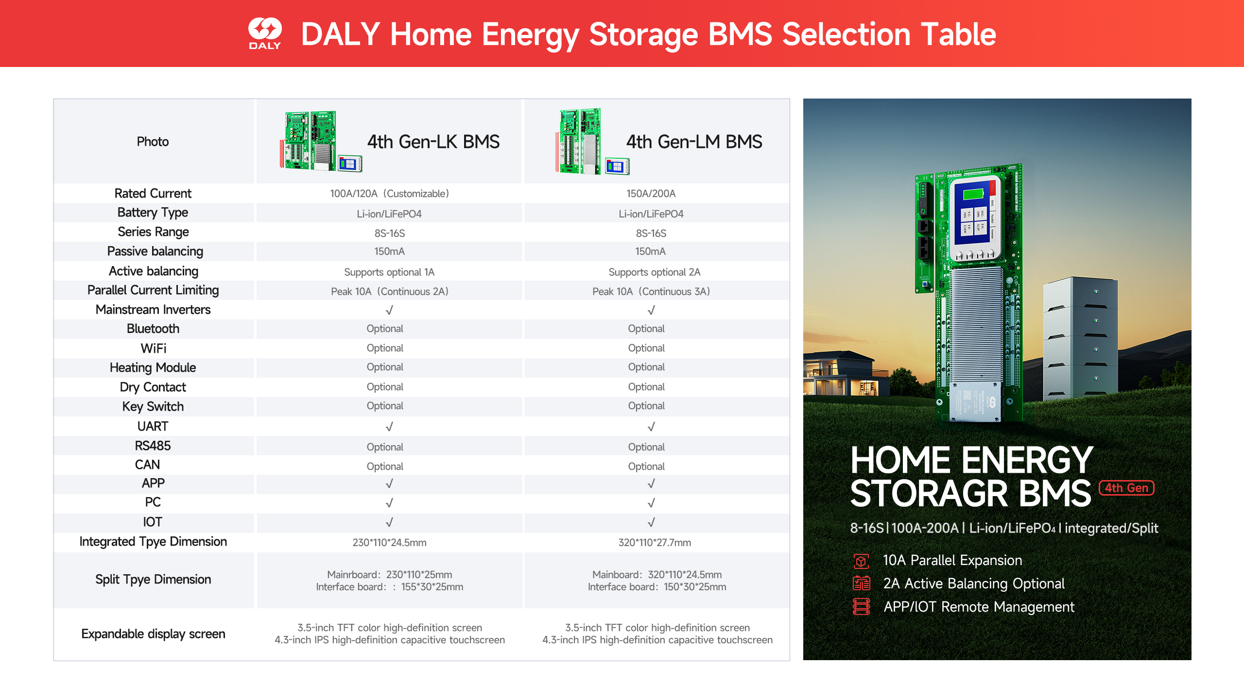
The latest DALY 4th-generation LK/LM comparison sheet provided for this article lists LiFePO4 8S/16S configurations and the following continuous charge/discharge current options. These are candidate ratings, not an automatic match to a given inverter.
LK: 100A continuous charge/discharge rating. LM: 150A or 200A continuous charge/discharge rating. The comparison sheet also identifies optional active balancing; do not assume every unit includes it.
For a design estimated to draw approximately 116A under one operating condition, a 100A continuous rating would not meet that estimated condition. A 150A option may be worth evaluating, but final selection still requires checks of minimum pack voltage, current peaks, charge current, thermal conditions, configuration, and the exact product datasheet.
For an initial technical review, provide: battery chemistry and series count (for example, 16S LiFePO4); pack capacity (Ah); cell voltage limits; inverter manufacturer/model and continuous/surge power; required continuous charging and discharging current; peak current and duration; communication requirements; expected installation temperatures; number of packs in parallel; and expected order quantity.
DALY can use this information to evaluate suitable LK/LM configurations, identify any information still needed, and discuss available technical documents and quotation options. Final model selection and protocol support must be confirmed for the requested configuration.
Share your 16S battery specification, inverter model, continuous and peak current requirements, communication needs, and planned order quantity. Ask DALY for a technical selection review, available datasheets, and a quotation.
Confirm the current RFQ form URL before publication.
Post time: Oct-14-2026


