
I.Introduction
The DL-R10Q-F8S24V150A product is a software protection board solution specifically designed for automotive starting power battery packs. It supports the use of 8 series of 24V lithium iron phosphate battery batteries and uses an N-MOS scheme with a one click forced start function
The entire system adopts AFE(front-end acquisition chip) and MCU, and some parameters can be flexibly adjusted through the upper computer according to customer needs.
II. Product Overview and Features
1. The power board uses aluminum substrate with high current wiring design and process, which can withstand large current impacts.
2. The appearance adopts the injection molding sealing process to improve moisture resistance, prevent the oxidation of components, and prolong the service life of the product.
3. dust proof, shockproof, anti-squeezing and other protective functions.
4. There are complete overcharge, over-discharge, over-current, short circuit, equalization functions.
5. The integrated design integrates acquisition, management, communication and other functions into one.
III. Communication Description
1. UART communication
This machine defaults to UART communication with a baud rate of 9600bps. After normal communication,the battery pack data can be viewed from the upper computer, including battery voltage, current, temperature, SOC, BMS status, cycle times, historical records, and battery production information. Parameter settings and corresponding control operations can be performed, and program upgrade functions are supported.
2. CAN communication
This machine supports CAN communication configuration, with a default baud rate of 250Kbps. After normal communication, various information of the battery can be viewed on the upper computer, including battery voltage, current, temperature, status, SOC, and battery production information. Parameter settings and corresponding control operations can be carried out, and program upgrade function is supported. The default protocol is lithium CAN protocol, and protocol customization is supported.
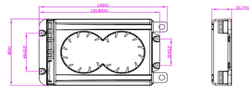
IV. Dimensional drawing of BMS
BMS Size: Long * Width * High (mm) 140x80x21.7
V. Key Function Description
Button wake-up: When the protection board is in a low-power sleep state, briefly press the button for 1s ±0.5s to wake up the protection board;
Key forced start: When the battery is under voltage or other discharge related faults occur, the BMS will turn off the discharge MOS tube, and at this time, the car cannot start the ignition. By pressing and holding the key for 3S ± 1S, the BMS will forcibly close the discharge MOS for 60S ± 10S to meet the power demand under special circumstances;
Attention: If the forced start switch is pressed, the MOS forced close function will fail, and it is necessary to investigate whether there is a short circuit outside the battery pack.
VI. Wiring Instructions
1. Firstly, connect the protective board B- line to the main negative electrode of the battery pack;
2. The collection cable starts from the first black wire connecting B-, the second wire connecting the positive pole of the first string of batteries, and then sequentially connects the positive pole of each string of batteries; Insert the cable into the protective board again;
3. After the line is completed, measure whether the battery B+, B- voltage and P+, P- voltage values are the same, indicating that the protection board is working normally; Otherwise, please follow the above instructions again;
4. When disassembling the protection board, first unplug the cable (if there are two cables, unplug the high-voltage cable first and then the low-voltage cable), and then remove the power cable B-.
VII. Precautions
1. BMS of different voltage platforms cannot be mixed. For example, NMC BMSs cannot be used on LFP batteries.
2. The cables of different manufacturers are not universal, please make sure to use our company’s matching cables.
3. Take measures to discharge static electricity when testing, installing, touching and using the BMS.
4. Do not let the heat dissipation surface of the BMS directly contact the battery cells, otherwise the heat will be transferred to the battery cells and affect the safety of the battery.
5. Do not disassemble or change BMS components by yourself
6. The company’s protective plate metal heat sink has been anodized and insulated. After the oxide layer is damaged, it will still conduct electricity. Avoid contact between the heat sink and the battery core and nickel strip during assembly operations.
7. If the BMS is abnormal, please stop using it and use it after the problem is solved.
8. Do not use two BMS in series or parallel.
Post time: Sep-08-2023


