
You connect the inverter to the battery output. The BMS trips immediately, before the inverter even powers on. Remove it, the BMS resets. Reconnect it, trips again. Every time, within a fraction of a second of making contact.
Nothing is wrong with the inverter. Nothing is wrong with the battery. The BMS is responding correctly to a real electrical event, one that looks identical to a short circuit but is not.
Quick Reference
| Symptom | Cause | Fix |
| BMS trips immediately at inverter connection | Capacitive inrush triggers short-circuit protection | Use a BMS with built-in pre-charge, or add an external pre-charge circuit |
| Works with small resistive loads, fails with inverter | Confirms inrush is the issue, not current rating | Pre-charge is required. A higher-current BMS alone will not solve this |
| BMS trips only under inverter full load | Load current exceeds BMS continuous rating | Verify inverter load against BMS continuous current rating |
| Trips at motor controller connection | Same capacitive inrush behavior | Same pre-charge solution |
What Is Happening Inside the Inverter
Modern inverters contain large DC-bus capacitors that smooth the DC voltage ripple as the inverter switches high-frequency AC internally. Capacitance scales with inverter power, ranging from a few thousand microfarads in small units to tens of thousands in 3 to 5 kW class units.
When the capacitors are fully discharged (as they are every time you connect the inverter for the first time, or after any power interruption), connecting them directly to the battery creates a brief but enormous current surge as the capacitors charge from zero to battery voltage in microseconds.
Without pre-charge, this inrush can produce instantaneous current spikes of several thousand amps within microseconds, exceeding even the peak rating of high-current BMS units. The BMS short-circuit protection responds to exactly this kind of event, a massive instantaneous current spike. It cannot distinguish between a dead short (a dangerous fault) and a capacitive inrush (normal electrical behavior). It fires both times.
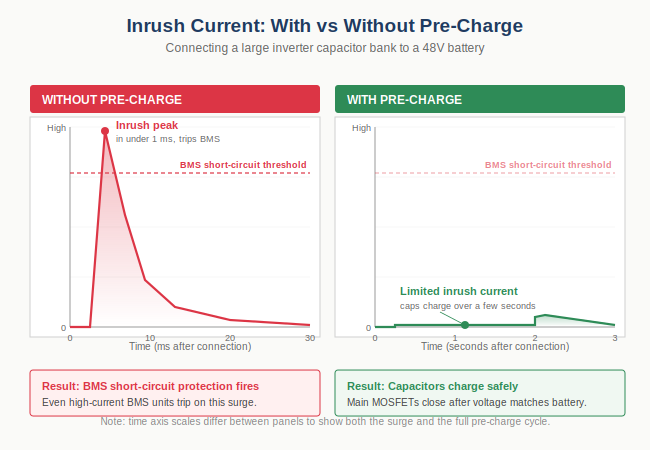
Figure 1. Inrush current waveform without pre-charge (left) versus with pre-charge (right). The unrestricted surge briefly exceeds the BMS short-circuit threshold regardless of the BMS continuous rating.
This is why a higher-current BMS alone does not solve the problem. Even a high-continuous-current BMS still trips on a high-capacitance inverter, because the instantaneous inrush briefly exceeds even peak ratings. Pre-charge is required regardless of BMS continuous current capacity.
True Short Versus Capacitive Inrush: How to Tell the Difference
Before changing equipment, confirm that inrush is the cause and not a genuine wiring fault.
Test: Disconnect the inverter completely. Connect only a small resistive load, a 100W light bulb, a resistor, anything with no capacitors. If the BMS holds without tripping, the problem is with the inverter connection specifically, not the BMS or wiring.
The event-log diagnostic: When a DALY BMS trips, it logs the trigger type (short circuit, over-current, capacitive inrush) along with measured terminal voltages at the moment of the event. Connect via the Bluetooth app and read the event log. The recorded trigger type and associated values reveal whether the event was a true short or an inrush trip. Different BMS series use different internal voltage thresholds for this classification, so consult the model-specific manual for diagnostic parameters, or contact engineering for series-specific details.
The Solution: Pre-Charge, Built-In or External
A pre-charge circuit limits the rate at which the inverter's DC-bus capacitors charge, so the surge stays below the BMS short-circuit threshold. There are two ways to implement it.
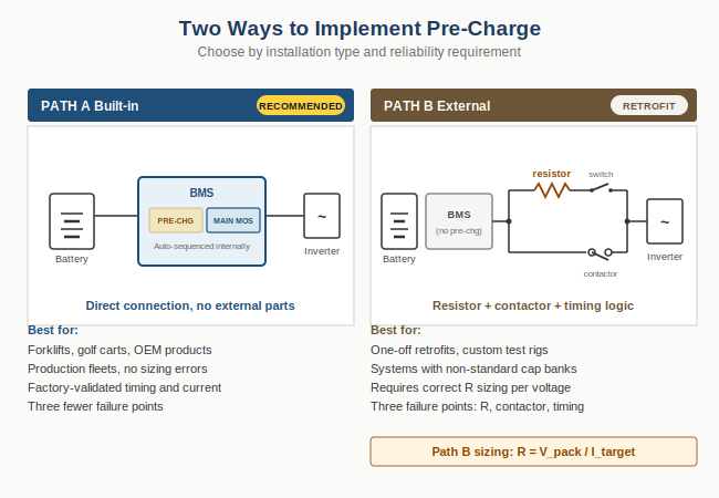
Figure 2. Two implementation paths. Path A uses a BMS with internal pre-charge logic. Path B uses an external resistor and contactor for BMS without built-in pre-charge.
Path A: BMS with Built-In Pre-Charge (recommended for production systems)
Several DALY BMS series include a built-in pre-charge circuit that handles capacitor charging automatically. No external resistor, relay, or timing logic required. Connect the inverter directly to the BMS output, and the internal pre-charge stage limits inrush before the main MOSFETs close.
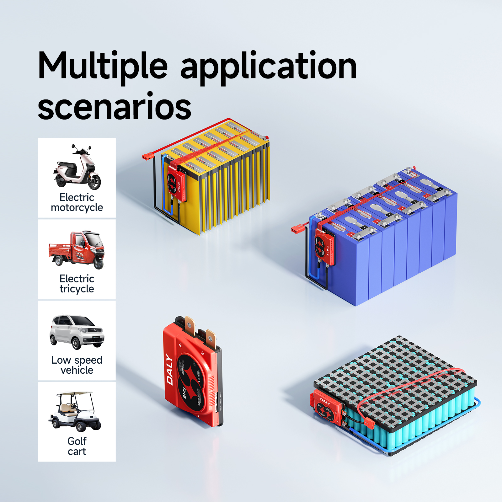
Built-in pre-charge is available across the DALY product range, including high-current series designed for inverter and motor-drive applications, mid-range balancer series, home-storage modules, and low-voltage high-power BMS targeting forklifts and golf carts. The internal pre-charge stage closes first, charges the inverter capacitors at a limited current, then closes the main discharge path once capacitor voltage matches battery voltage. The full sequence typically completes within 500 ms to a few seconds depending on capacitor size.
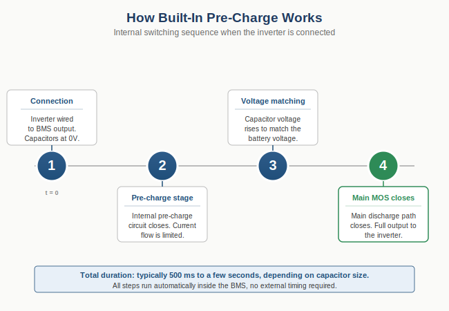
Figure 3. Internal switching sequence of a BMS with built-in pre-charge. All steps run automatically with no external timing or relay required.
Path B: BMS Without Built-In Pre-Charge (external circuit)
If your BMS does not include built-in pre-charge, you need to add an external pre-charge circuit. The standard topology:
1. Insert a pre-charge resistor in series between BMS output and inverter DC input, bypassed by a contactor.
2. On initial connection, current flows only through the resistor. Capacitors charge slowly.
3. After a defined delay (typically a few seconds for large capacitor banks), the contactor closes and bypasses the resistor.
4. The inverter now receives full BMS output.
Sizing the resistor by Ohm's Law: R = V_pack / I_target.
| Pack Voltage | Target Peak Inrush | Resistor (minimum) |
| 48V system | 10A | R >= 4.8 ohm (use 5 ohm, 50W) |
| 72V system | 10A | R >= 7.2 ohm (use 8 ohm, 80W) |
| 96V system | 10A | R >= 9.6 ohm (use 10 ohm, 100W) |
Resistor wattage must handle the surge energy: P_surge = 0.5 x C x V squared, delivered over the pre-charge interval. A 50W ceramic resistor with 100W short-time rating handles most low-voltage installations.
Implementation options:
| Option | When to use | Components |
| Manual pre-charge | Service vehicles where operator is present at every connection | Resistor and manual switch |
| Time-delay relay | Permanent installations, fixed inverter setups | Resistor, time-delay relay, and contactor |
| Microcontroller-driven | Custom OEM products, variable load conditions | Resistor, MCU, and relay or SSR |
| Need a pre-charge configuration verified for your specific system?Our engineering team responds within 24 hours with a sized configuration. To get an accurate response, please provide:1. Inverter model and DC-bus capacitance (microfarads)
2. Pack nominal voltage (V) 3. Expected continuous and peak discharge current (A) 4. Application type (inverter, motor controller, forklift, golf cart, or other) Submit request: https://www.dalyelec.com/large-current-bms |
When Built-In Pre-Charge Makes More Sense Than an External Circuit
External pre-charge works, but adds three failure points to your installation: a resistor that must be sized correctly for surge energy, a relay or switch that must be timed correctly for your specific capacitor bank, and wiring that must withstand both the surge current and continuous load current.
For production installations such as forklifts, golf carts, off-grid inverter cabinets, and motor-drive OEM units, built-in pre-charge eliminates all three. The BMS handles capacitor charging internally with factory-validated timing and current limits, so there is nothing to size, nothing to fail, and nothing to wire wrong.
DALY BMS for Inverter and Motor-Drive Applications
DALY offers BMS products with built-in pre-charge across multiple series, covering the full power range from home-storage modules through low-voltage high-power systems for forklifts, golf carts, and off-grid inverters. Every series with built-in pre-charge supports direct inverter connection. Continuous-current capability, peak surge tolerance, communication interfaces, and configurable thresholds vary by model. Contact engineering with your load profile to identify the right match.
View DALY BMS catalogue: https://www.dalyelec.com/large-current-bms
For a complete guide to BMS protection triggers and how to identify each one, see Why Does My BMS Keep Shutting Off? 7 Causes and Fixes.
Frequently Asked Questions
Why does the BMS trip the inverter but not a power tool of the same wattage?
Power tools and resistive loads have no large input capacitors. They draw current proportional to their actual operating load, which ramps up over milliseconds. Inverters draw a capacitor-charging surge in microseconds. These look entirely different to the BMS protection circuit, which must respond in under a millisecond.
My inverter has a soft-start feature. Do I still need pre-charge?
In most cases, yes. Inverter soft-start circuitry typically limits inrush on the AC output side. It does not affect the DC input capacitor charging behavior. Some premium grid-tied PCS units integrate DC-side pre-charge. If your inverter datasheet explicitly states integrated DC pre-charge or DC inrush limiter, you can connect directly. Otherwise, external or built-in BMS pre-charge is required.
How large a resistor do I need for an external pre-charge circuit?
Calculate by R = V_pack / I_target. For a 48V system limiting peak inrush to 10A, use R >= 4.8 ohm. Larger inverters with bigger capacitor banks need longer pre-charge time at the same resistor value, not a different resistor. Adjust the contactor delay, not the resistance. Also size the resistor wattage to handle surge energy.
I bought a high-current BMS and it still trips when I connect a large inverter. Why?
Continuous current rating and inrush handling are unrelated. A BMS rated for high continuous current can still trip on a high-capacitance inverter, because the inrush spike, several thousand amps for microseconds, briefly exceeds even peak current ratings. The fix is pre-charge, not a higher-rated BMS. Choosing a BMS with built-in pre-charge addresses both requirements in one unit.
How do I choose between built-in BMS pre-charge and an external pre-charge circuit?
Built-in pre-charge eliminates external wiring and matched-component sourcing. This is ideal for production fleets and OEM integrations where reliability and assembly time matter. External pre-charge circuits give finer control over timing and resistor selection. They are useful for one-off retrofits, custom test setups, or systems with non-standard capacitor banks. For an engineering recommendation matched to your specific load profile, send your inverter model, pack voltage, and application type to our team. Reply within 24 hours.
Summary
| Problem | Cause | Solution |
| BMS trips at inverter connection | Capacitive inrush (thousands of amps within microseconds) exceeds short-circuit threshold | Use a BMS with built-in pre-charge, or add external pre-charge |
| Higher-current BMS still trips | Inrush is a microsecond spike, unrelated to continuous current rating | Pre-charge, not a larger BMS |
| Works with small loads, trips with inverter | Confirms inrush, not current rating | Pre-charge required. Check event log for trigger type |
| External pre-charge complex to size correctly | Resistance, surge energy, and timing all need matching | Built-in pre-charge eliminates sizing. Direct connection works |
Data sources: DALY product technical documentation (2026). External pre-charge circuit topology aligned with IEC 60204-1.
Post time: May-16-2026


