
I. Introduction
1. With the widespread application of iron lithium batteries in home storage and base stations, requirements for high performance, high reliability, and high-cost performance are also proposed for battery management systems. DL-R16L-F8S/16S 24/48V 100/150ATJ is a BMS designed specifically for energy storage batteries. It adopts an integrated design that integrates functions such as acquisition, management, and communication.
2. The BMS product takes integration as the design concept and can be widely used in indoor and outdoor energy storage battery systems, such as home energy storage, photovoltaic energy storage, communication energy storage, etc.
3. The BMS adopts an integrated design, which has higher assembly efficiency and testing efficiency for Pack manufacturers, reduces production input costs, and greatly improves the overall installation quality assurance.
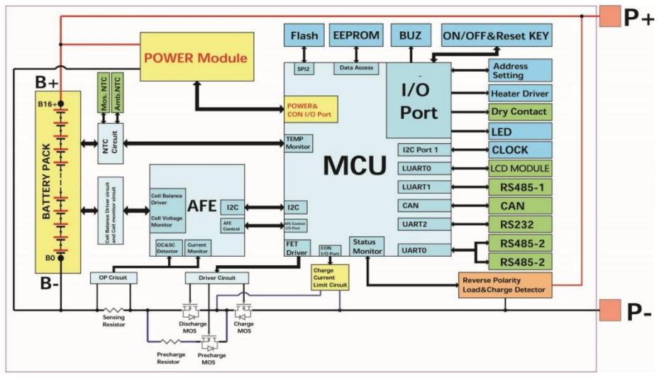
II. System block diagram
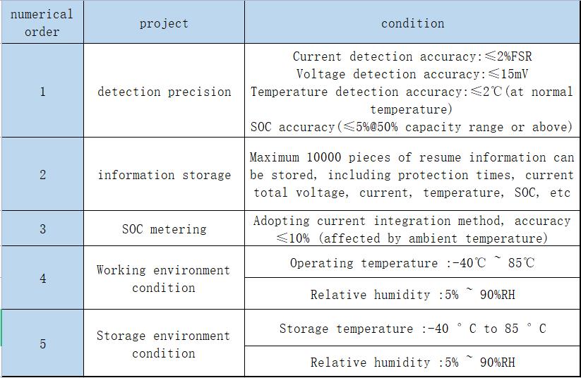
III. Reliability Parameters
IV. Button description
4.1.When the BMS is in sleep mode, press the button for (3 to 6S) and release it. The protection board is activated and the LED indicator lights up successively for 0.5 seconds from "RUN".
4.2.When the BMS is activated, press the button for (3 to 6S )and release it. The protection board is put to sleep and the LED indicator lights up successively for 0.5 seconds from the lowest power indicator.
4.3.When the BMS is activated, press the button (6-10s) and release it. The protection board is reset and all LED lights are off at the same time.
V. Buzzer logic
5.1.When the fault occurs, the sound is 0.25S every 1S.
5.2.When protecting, chirp 0.25S every 2S (except for over-voltage protection, 3S ring 0.25S when under-voltage);
5.3.When an alarm is generated, the alarm buzzes for 0.25S every 3S (except the over-voltage alarm).
5.4.The buzzer function can be enabled or disabled by the upper computer but is forbidden by factory default.
VI. Wake up from sleep
6.1.Sleep
When any of the following conditions are met, the system enters the sleep mode:
1) Cell or total under-voltage protection is not removed within 30 seconds.
2) Press the button (for 3~6S) and release the button.
3) No communication, no protection, no bms balance, no current, and the duration reaches the sleep delay time.
Before entering hibernation mode, ensure that no external voltage is connected to the input terminal. Otherwise, the hibernation mode cannot be entered.
6.2.Wake up
When the system is in sleep mode and any of the following conditions are met, the system exits hibernation mode and enters normal operation mode:
1) Connect the charger, and the output voltage of the charger must be greater than 48V.
2) Press the button (for 3~6S) and release the button.
3) With 485, CAN communication activation.
Note: After cell or total under-voltage protection, the device enters sleep mode, wakes up periodically every 4 hours, and starts charging and discharging MOS. If it can be charged, it will exit the resting status and enter normal charging; If the automatic wake-up fails to charge for 10 consecutive times, it will no longer wake up automatically.
VII. Description of communication
7.1.CAN communication
The BMS CAN communicates with the upper computer through the CAN interface, so that the upper computer can monitor various information of the battery, including battery voltage, current, temperature, status, and battery production information. The default baud rate is 250K, and the communication rate is 500K when interconnecting with the inverter.
7.2.RS485 communication
With dual RS485 ports, you can view PACK information. The default baud rate is 9600bps. If you need to communicate with the monitoring device over the RS485 port, the monitoring device serves as the host. The address range is 1 to 16 based on the address polling data.
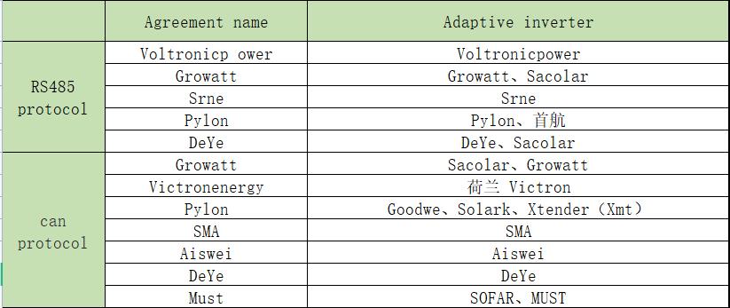
VIII. Inverter communication
The protection board supports the inverter protocol of RS485 and CAN communication interface. The engineering mode of the upper computer can be set.
IX.Display screen
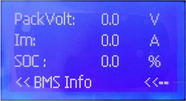
9.1.Main page
When the battery management interface is displayed:
Pack Vlot: Total battery pressure
Im: current
SOC: State Of Charge
Press the ENTER to enter the home page.
(You can select items up and down, then press the ENTER button to enter, long press the confirmation button to switch English display)
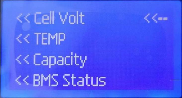
Cell Volt:Single-unit voltage query
TEMP:Temperature query
Capacity:Capacity query
BMS Status: A BMS status query
ESC: Exit (under the entry interface to return to the superior interface)
Note: If the inactive button exceeds 30s, the interface will enter a dormant Status; awaken the interface with any boundary.
9.2. Power consumption specification
1)Under the display Status, I complete machine = 45 mA and I MAX = 50 mA
2)In the sleep mode, I complete machine = 500 uA and I MAX = 1 mA
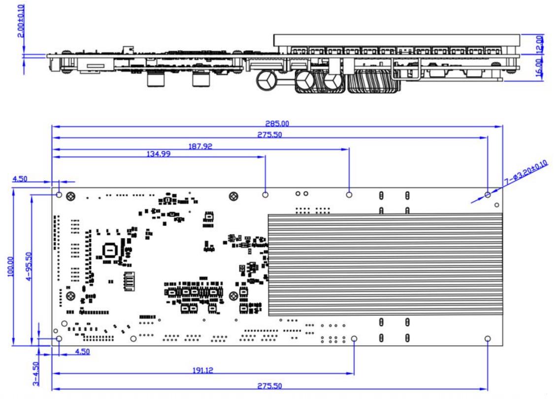
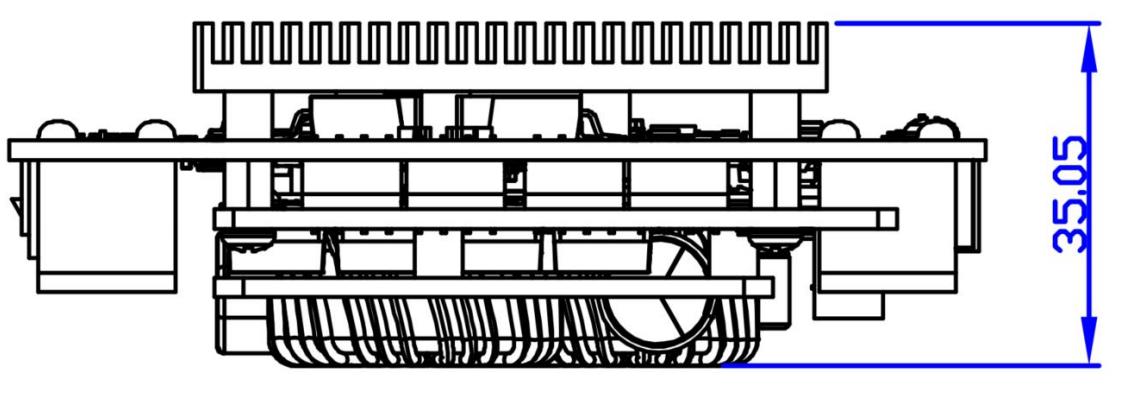
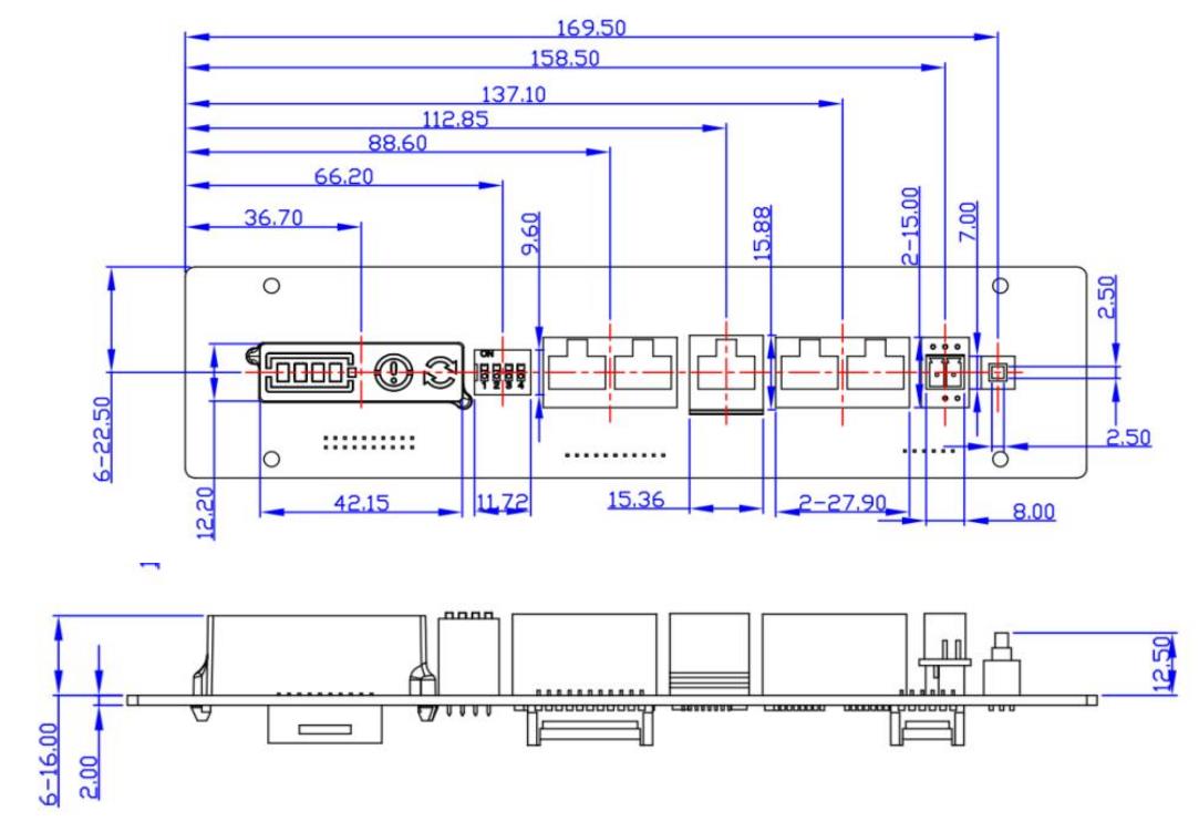
X. Dimensional drawing
BMS size: Long * Width * High (mm): 285*100*36
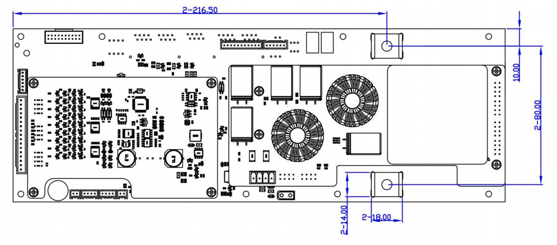
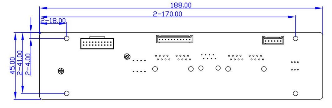
XI. Interface board size
XII. The wiring instructions
1. Protection board B - first with the power line received a battery pack the cathode;
2. The row of wires starts with the thin black wire connecting B-, the second wire connecting the first series of positive battery terminals, and then connecting the positive terminals of each series of batteries in turn; Connect the BMS to the battery, NIC, and other wires. Use the sequence detector to check that the wires are correctly connected, and then insert the wires into the BMS.
3. After the wire is finished, press the button to wake up the BMS, and measure whether the B+, B- voltage, and P+, P- voltage of the battery are the same. If they are the same, the BMS works normally; Otherwise, repeat the operation as above.
4. When removing the BMS, remove the cable first (if there are two cables, remove the high-pressure cable first, and then the low-pressure cable), and then remove the power cable B-
XIII. Points for attention
1. BMS of different voltage platforms cannot be mixed;
2. The wiring of different manufacturers is not universal, please make sure to use our company's matching wiring;
3. When testing, installing, touching, and using the BMS, take ESD measures;
4. Do not make the radiator surface of the BMS contact the battery directly, otherwise the heat will be transferred to the battery, affecting its safety of the battery;
5. Do not disassemble or change BMS components by yourself;
6. If the BMS is abnormal, stop using it until the problem is resolved.
Post time: Aug-19-2023


