
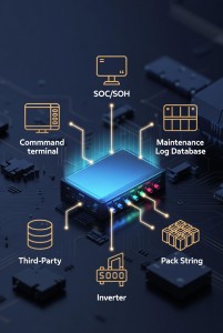
Modern battery systems do not operate in isolation. Whether you are managing a residential solar installation, a commercial energy storage rack, or an industrial EV fleet, your BMS needs to communicate — with inverters, monitoring platforms, building management systems, and remote dashboards.
This guide covers how DALY Smart BMS connects to IoT infrastructure as an RS485 BMS, CAN bus BMS, and Bluetooth-enabled device, and how to integrate BMS data into SCADA and energy management platforms via standard RS485 BMS communication protocols.

Why Communication Protocol Matters for B2B BMS Buyers
A BMS that only protects cells is a 2010-era solution. Today's B2B buyers require BMS units that can:
- Report real-time SOC, SOH, cell voltages, and temperature to a central monitoring system
- Accept remote commands: charge enable, discharge enable, wake/sleep
- Log historical data for preventive maintenance and warranty management
- Interface with third-party inverters, chargers, and energy management systems
- Support multi-pack parallel communication in large battery string configurations
The protocol your BMS supports determines which capabilities are available and which third-party systems it is compatible with.
DALY Smart BMS Communication Protocols
RS485 — MODBUS RTU
RS485 is the dominant industrial communication standard for RS485 BMS-to-SCADA integration. It uses a two-wire differential signal supporting cable runs up to 1,200 meters and multi-device networks with up to 32 nodes per segment. An RS485 BMS can communicate with SCADA platforms, inverters, and energy management systems using the MODBUS RTU protocol.
| RS485 Parameter | DALY Smart BMS Specification |
| Protocol | MODBUS RTU |
| Baud rate | 9600 bps default; configurable to 115200 bps |
| Data frame | 8N1 (8 data bits, no parity, 1 stop bit) |
| Readable data | Per-cell voltage, pack voltage, current, SOC, SOH, temperature (4× NTC), protection flags, cycle count |
| Writable commands | Charge enable/disable, discharge enable/disable, balance on/off, SOC calibration |
| Compatible systems | Growatt, Deye/Sunsynk, Modbus-capable SCADA (Ignition, Wonderware, WinCC, Home Assistant) |
Full register documentation is available for download at /daly-product-manual/
CAN Bus — SAE J1939 / Custom Frame
CAN bus is the standard for automotive and heavy industrial applications. It offers faster communication speeds than RS485, deterministic timing, and built-in error detection — preferred for EV BMS, commercial vehicle battery systems, and grid-scale energy storage.
| CAN Parameter | DALY Smart BMS Specification |
| Standard | CAN 2.0B |
| Speed | 250 kbps / 500 kbps selectable |
| Frame format | Extended ID (29-bit) |
| Protocol variants | Custom DALY frame (documented); SAE J1939 compatible on request |
| Applications | EV charging stations, commercial vehicle BMS, industrial battery strings, telecom backup |
Bluetooth — BLE 4.0/5.0 + Mobile App
For installations where wired communication is impractical — residential storage, RV systems, portable packs — DALY Smart BMS includes BLE connectivity with a free iOS/Android application.
- Real-time display: cell voltages per cell, pack voltage, current, SOC, SOH estimate
- Temperature monitoring: up to 4 sensor points
- Protection log: timestamped history of all triggered protection events
- Parameter configuration: adjust voltage and current thresholds within factory-defined safe limits
- OTA firmware update: supported on applicable models
UART — Direct Serial
Used for direct microcontroller integration in custom OEM designs where the BMS communicates with an embedded controller. Full UART protocol documentation available for OEM customers under NDA.

Connecting DALY Smart BMS to SCADA Platforms
Standard Integration Path: RS485 → MODBUS RTU
The most common integration path for commercial and industrial installations:
| Layer | Component | Notes |
| BMS | DALY Smart BMS | RS485 port standard on all models |
| Field bus | RS485 two-wire cable | Up to 1,200m; 120Ω termination at each end |
| Gateway | RS485-to-TCP/IP converter | e.g., Moxa MB3170, Advantech Adam-4570 |
| Platform | SCADA / EMS software | Any MODBUS TCP-capable system |
| Output | Dashboard / alerts / data log | SOC, cell health, protection events |
Inverter Integration
For solar energy storage, the BMS communicates with the inverter to coordinate charge and discharge behavior. The BMS reports SOC and voltage limits; the inverter adjusts charge current accordingly.
- Growatt (RS485 MODBUS) — tested compatible with DALY RS485 MODBUS implementation; register map at /daly-product-manual/
- Deye / Sunsynk (RS485) — tested compatible with DALY RS485 MODBUS implementation; register map at /daly-product-manual/
- Victron Energy — via protocol converter (Victron GX device with custom driver)
- SMA, Fronius — custom CAN integration available on request → See also: DALY Communication Protocols Explained: /news/daly-three-communication-protocols-explanation/ → BMS-to-Inverter Wiring Guide: /news/how-to-wire-daly-bms-to-the-inverter/
Multi-Pack Parallel Communication
Large battery systems use multiple BMS units in a master-slave configuration. DALY supports RS485 daisy-chain topology with addressable device IDs (1–247). One master BMS aggregates data from all slave units. SCADA reads the master BMS for system-level data.
Maximum string configuration: up to 16 BMS units per RS485 segment before requiring a repeater.
Specification Summary for Integration Planning
| Parameter | What to Verify | DALY Smart BMS |
| Protocol | RS485 / CAN / BLE — which does your system require? | All three standard |
| Baud rate | Must match gateway or inverter setting | Configurable |
| Register documentation | Full MODBUS map available for integrator? | Yes — downloadable |
| Update rate | How often does BMS transmit data? | 100 ms–1 s configurable |
| Multi-pack topology | Master-slave support for large strings? | Yes, up to 16 units |
| OEM customization | Protocol customizable for OEM integration? | Yes — NDA required |
| Certifications | CE, UN38.3 for export compliance? | CE + UN38.3 standard |
Product Configurations
DALY Smart BMS is available in the following series configurations:
Cell series: 4S / 7S / 8S / 10S / 12S / 13S / 14S / 15S / 16S / 17S / 20S / 24S
Current ratings: 40A / 60A / 80A / 100A / 150A / 200A / 250A / 300A
Chemistry: LiFePO4 (3.2V/cell) · NMC (3.7V/cell) · NCA · LTO (2.4V/cell)
All units include RS485 and Bluetooth as standard. CAN bus and UART available on selected models or as OEM option.
Frequently Asked Questions
Does DALY BMS support MODBUS TCP directly?
DALY Smart BMS natively supports MODBUS RTU over RS485. For MODBUS TCP, use a standard RS485-to-TCP gateway — a common, low-cost component available from Moxa, Advantech, and similar suppliers.
Can BMS parameters be configured remotely via RS485?
Yes. Writeable registers allow remote adjustment of voltage thresholds, current limits, and balance settings. The full write register list is available in the protocol documentation.
What is the maximum RS485 cable length?
Up to 1,200 meters with 120Ω termination resistors at each end of the bus. Use a signal repeater for longer runs.
Is protocol documentation available for third-party integrators?
RS485 MODBUS register maps are publicly available on the download page. CAN bus frame documentation and UART protocol specifications are available for OEM customers under NDA.
| Get Technical Support for Your IntegrationDALY BMS supports B2B customers with pre-sale technical consultation, protocol documentation, and post-sale integration support. Contact: /contact/ · Smart BMS products: /smart-bms/ · Protocol docs: /daly-product-manual/ · Communication guide: /news/daly-three-communication-protocols-explanation/ · Wiring guide: /news/how-to-wire-daly-bms-to-the-inverter/ |
Post time: Apr-16-2026


