

Introduction
Choosing a battery management system (BMS) current rating for a home energy storage battery is not simply a matter of matching the BMS to the battery capacity in amp-hours (Ah). The more useful starting point is the maximum current the battery pack must deliver or accept during normal operation, including the effect of inverter power, battery voltage, and conversion efficiency.
For example, a customer with a 5 kilowatt (kW) inverter may assume that a 100 ampere (A) BMS is sufficient for a 48-volt-class battery. That assumption may be wrong if the battery voltage falls under load or if the inverter operates near its rated output for an extended period.
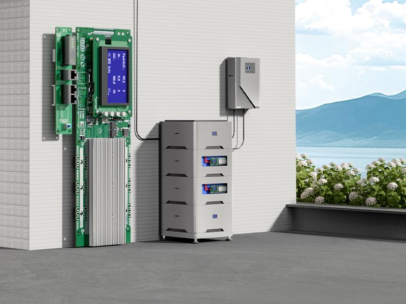
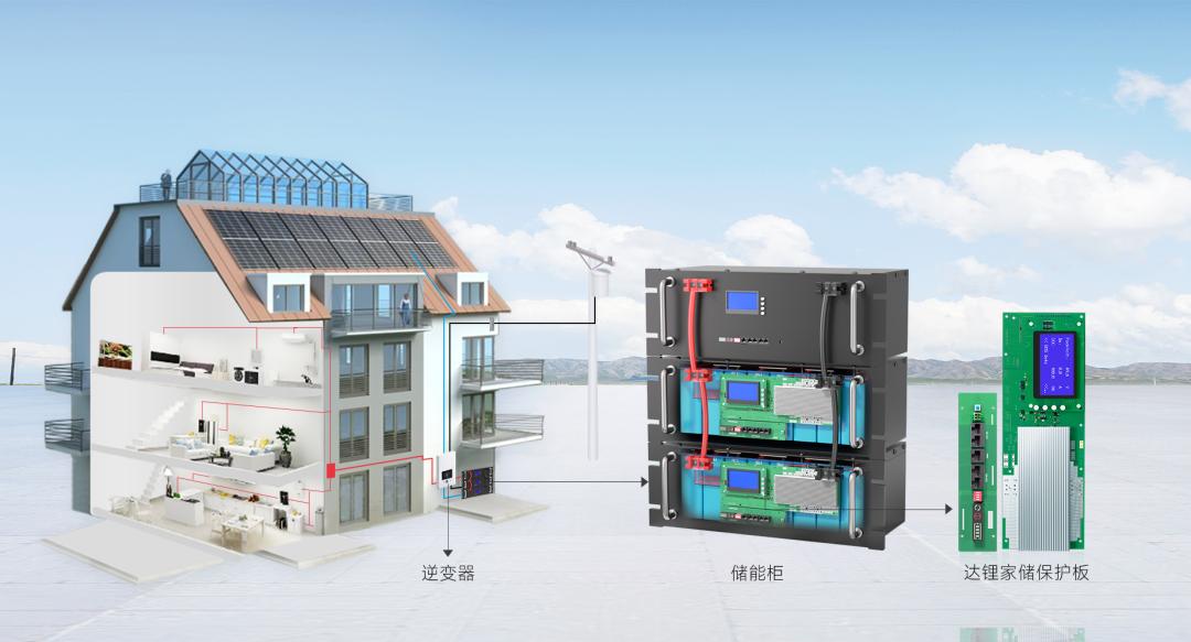
This guide explains how to estimate the battery-side discharge current, how to check charging current separately, and how to compare the result with the continuous current ratings of DALY’s 4th Generation LK and LM home energy storage BMS models.
1. Start with the Battery-Side Current, Not Only the Ah Rating
Battery capacity, measured in amp-hours (Ah), describes how much charge a battery can store under specified conditions. It does not, by itself, tell you the maximum current the battery must deliver to an inverter.
A 100 Ah battery pack could be used with different inverter power levels and operating profiles. The required BMS current therefore depends on the system’s power demand and the battery’s operating voltage, as well as the limits of the cells and the rest of the electrical system.
For an inverter supplying alternating-current (AC) power from a battery, estimate the direct-current (DC) current drawn from the battery using:
- IDC = estimated DC current drawn from the battery, in amperes (A)
- PAC = inverter AC output power, in watts (W)
- Vbattery = battery voltage at the operating condition being evaluated, in volts (V)
- η = inverter conversion efficiency expressed as a decimal (for example, 90% = 0.90)
This is an estimate for the discharge direction. Use the inverter manufacturer’s specifications for rated output power, efficiency, and minimum operating battery voltage wherever available. A calculation using nominal battery voltage alone can understate current when the battery voltage is lower.
2. Worked Example: A 5 kW Inverter on a 48 V-Class Battery
The following example is illustrative, not a universal battery-voltage specification. Assume an inverter must deliver 5,000 watts (W) AC, the battery voltage at the operating point is 44 volts (V), and inverter efficiency at that operating point is assumed to be 90%. These two operating values are example assumptions, not DALY product specifications.
Under these stated assumptions, the estimated battery-side discharge current is approximately 126 A. A BMS with a 100 A continuous rating would not meet this calculated operating condition if the battery must continuously supply the full 5,000 W output at the assumed 44 V and 90% efficiency. A 150 A continuous option may be a candidate for further evaluation, but it is not automatically approved by this calculation.
The final design must also check the inverter’s actual DC input limits, the battery cells’ permitted continuous discharge current, wiring and connector ratings, fuses or other overcurrent protection, thermal conditions, and any surge requirement.
3. Compare the Result with the BMS Continuous Current Rating
After estimating the required battery-side current, compare it with the continuous charge/discharge current rating published for the exact BMS model and configuration being considered.
| DALY model | Published continuous current rating | Initial interpretation |
|---|---|---|
| 4th Generation LK | 100 A | Consider only where the verified continuous requirement is within the rating and all other system limits are satisfied. |
| 4th Generation LM | 150 A or 200 A | Evaluate where the verified continuous requirement is higher than 100 A but remains within the selected rating and system limits. |
These are the published LK and LM continuous current options used in this article. Do not infer an unlisted standard rating or assume that a customization is available without written confirmation for the requested configuration.
If the calculated continuous requirement is above 200 A, do not assume that connecting multiple BMS units in parallel automatically creates a suitable higher-current solution. The complete battery architecture, current sharing, protection strategy, and approved configuration must be reviewed by the engineering team.
4. Check Charging Current Separately
Discharge current is only one side of the selection. The BMS must also be suitable for the maximum charging current that the battery can receive from the inverter/charger, solar charger, or other charging source.
Obtain the maximum battery charging current from the charger or inverter documentation and compare it with the BMS charging-current specification and the cell manufacturer’s permitted charge current. Do not assume that the charging current is equal to the discharge current.
For a system with more than one charging source, establish the maximum simultaneous charging current under the intended operating conditions. The battery design and charging controls must be considered together.
5. Do Not Confuse Continuous Current with Peak or Surge Current
Some loads draw a short-duration surge when starting. Examples can include motors, pumps, compressors, and other equipment with high start-up demand. A system may therefore experience a peak current above its normal operating current.
Before selecting a BMS, identify both the continuous current and the peak current, including how long the peak lasts and how often it occurs. Then check the exact BMS documentation for the applicable peak-current limit, duration, and protection behavior. A continuous current rating must not be treated as a peak-current rating, and a peak figure must not be treated as a continuous rating.
6. Check the Whole Battery System, Not Just the BMS
The BMS rating does not independently determine the safe current capability of the complete battery pack. The actual system limit may be lower because of the cells, busbars, cables, connectors, fuses, terminals, thermal design, or inverter limits.
- Battery cells: confirm the cell manufacturer’s continuous charge and discharge current limits.
- Battery voltage: use the lowest relevant operating voltage for discharge-current estimation, not only nominal voltage.
- Cables and connections: confirm current ratings, installation conditions, and connection quality.
- Overcurrent protection: check fuse or breaker selection and coordination with the system design.
- Temperature: consider the battery and BMS operating environment and any temperature-related current restrictions.
- Inverter: confirm continuous power, surge power, DC voltage range, and maximum battery charge current.
The correct selection is the one that satisfies the requirements and limits of the complete system. Choosing a BMS with a higher nameplate current does not compensate for undersized cells, wiring, or protection devices.
7. How to Use This Calculation When Comparing DALY LK and LM
DALY’s 4th Generation LK and LM home energy storage BMS models are listed for 8S and 16S configurations (the number of cells connected in series) and Li-ion (lithium-ion) and LiFePO4 (lithium iron phosphate) battery chemistries in DALY’s product information. The published continuous charge/discharge current ratings are 100 A for LK and 150 A or 200 A for LM.
The current rating is only one part of the selection. The project should also confirm the exact battery series configuration, chemistry, inverter model, communication protocol, parallel-pack plan, and required optional functions. CAN (Controller Area Network) and RS-485 (a serial communication interface standard) are communication options on the platform; the presence of an interface does not by itself prove compatibility with every inverter model.
For parallel battery systems, do not multiply a single BMS rating by the number of packs and assume the result is the approved system current. Parallel configuration, current distribution, inter-pack communication, and protection limits need to be reviewed for the actual design.
8. Information to Prepare Before Asking for a BMS Recommendation
A useful technical inquiry should include the following information:
- Battery chemistry (for example, LiFePO4 or another Li-ion chemistry).
- Number of cells in series and the battery’s nominal and operating voltage range.
- Battery capacity (Ah) and cell model or cell datasheet, if available.
- Inverter manufacturer and exact model.
- Inverter continuous output power and surge power, including surge duration.
- Maximum required continuous battery discharge current.
- Maximum battery charging current and charging sources.
- Required peak current and its duration.
- Required communication interface and protocol (if inverter communication is needed).
- Number of battery packs planned for parallel operation.
- Installation temperature range and any optional functions required.
Conclusion
To select a BMS current rating for a home energy storage battery, start with the inverter’s power demand and calculate the battery-side current at the relevant battery voltage and inverter efficiency. Then check charging current, peak demand, cell limits, wiring, protection devices, temperature, and the exact BMS configuration.
For DALY’s 4th Generation home energy storage range, the published LK option is rated at 100 A continuous, while LM options are rated at 150 A or 200 A continuous. These ratings provide candidates for evaluation; the correct choice depends on the verified requirements and limits of the complete battery system.
Request a Technical BMS Selection Review
If you are developing a home energy storage battery pack, share your battery chemistry, series count, voltage range, inverter model, continuous and peak current requirements, charging current, and planned parallel-pack configuration with DALY. The technical team can review the information and confirm which LK/LM configuration, if any, is suitable for the project.
Technical references
- DALY — LK and LM Home Energy Storage BMS product overview
- DALY — 4th Generation 8S/16S and parallel-pack overview
- DALY — 48V LiFePO4 BMS selection guidance
- Samlex — Evolution inverter/charger owner’s guide
Note: The 44 V battery operating point and 90% inverter efficiency in the worked example are illustrative assumptions, not universal specifications. Use the actual inverter and battery documentation for a real system design.
Post time: Nov-09-2026


