

A lithium BMS — battery management system — is the circuit that stands between a lithium battery pack and the ways lithium cells fail. Any serious pack build, whether lithium-ion (NCM), LiFePO4, or LTO (lithium titanate), carries one, and specifying it comes down to four decisions: the chemistry and series count it must support, the continuous current it must carry, the communication interfaces the application needs, and the balancing method that keeps cells aligned over the pack's life.
This page walks through what a battery management system for lithium-ion and LiFePO4 packs actually does, then each of the four decisions in turn, with the specification ranges DALY covers at each step.
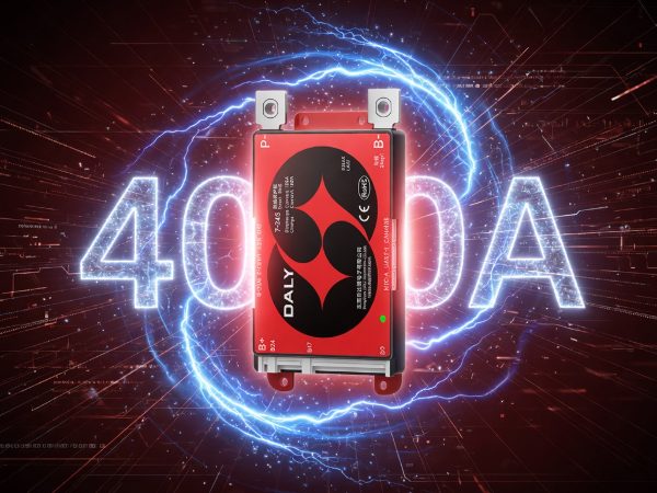
What a Lithium BMS Does
Every lithium BMS carries a baseline protection set: overcharge, over-discharge, overcurrent, temperature, and short-circuit protection. These are not premium features — they are the definition of the product category. The BMS monitors each cell group's voltage and the pack's current and temperature, and disconnects the main circuit when any reading crosses its protection threshold; recovery follows once conditions return to the safe window, with the exact recovery behavior depending on the fault type.
On top of that baseline, a smart BMS adds measurement you can see and settings you can change: cell-by-cell voltage readout, state of charge estimation, history logging, and a Bluetooth link to a phone app for monitoring and parameter configuration. The four decisions below determine which board carries those functions for your specific pack.
Decision 1 — Chemistry and Series Count
The first specification is what the pack is made of. DALY's Smart BMS (A Series) uses a 4–24S universal design (4 to 24 cells in series) covering the three mainstream lithium chemistries:
| Chemistry | Supported Series Range |
|---|---|
| LiFePO4 (LFP) | 4–8S / 7–17S / 7–24S |
| Lithium-ion (NCM) | 4–7S / 7–17S / 7–20S |
| LTO | 6–8S / 11–17S / 11–24S |
Two functions make the universal design practical in production. Chemistry is switchable in the DALY app with one tap, so the same board serves an LFP order this month and an NCM order next month. And series count is detected automatically within 45 seconds of first power-on — no DIP switches, no per-unit configuration — which means a 13S e-bike pack and a 16S 48V pack can ship from the same BMS stock.
Decision 2 — Continuous Current Tier
The current rating is the decision with the most direct cost consequence: over-specify and you pay for copper you never use; under-specify and the BMS disconnects under legitimate load. The A Series covers four tiers:
| Current Tier | Continuous | Peak |
|---|---|---|
| 40A / 60A | 40A / 60A | 60A / 90A |
| 80A / 100A | 80A / 100A | 120A / 150A |
| 150A / 200A | 150A / 200A | 225A / 300A |
| 250A–400A | 250A / 300A / 400A | 375A–600A |
Two checks specify the tier. First, match the continuous rating to the load's sustained draw, not its nameplate maximum. Second, check the peak column against the application's surge events — motor starts, inverter surges — because it is the peak rating, not the continuous one, that decides whether the BMS rides through them. Where a pack's requirement exceeds 400A continuous, the high-current BMS line takes over.
Decision 3 — Communication
A pack that only protects is functionally complete; a pack that reports is sellable at a better margin. The A Series ships with dual UART, RS485, and CAN as standard interfaces, plus built-in Bluetooth for the DALY app. Which one your application uses depends on what sits on the other end of the wire: inverters and chargers in storage and mobility systems typically take RS485 or CAN, while UART commonly serves display units and host controllers.
The practical specification question is not "which bus is best" but "what does the receiving device speak" — and because all three interfaces are on the same board, a single BMS model covers customers on different buses without a hardware change.
Decision 4 — Balancing
Cells drift apart over charge cycles, and the balancing method determines how much drift the BMS can correct. The A Series carries 100mA passive balancing as standard — sufficient to hold well-matched new cells in line in normal service.
When cell consistency is the constraint — large-capacity cells with wider spread, second-life cells, or packs that cycle deeply every day — the T Series active balancing BMS moves energy between cells at up to 1A using bidirectional transformer balancing, across the same 4–24S range, in current tiers from 40A to 400A. A 30A tier with 0.5A inductive active balancing is also available for small 12V LiFePO4 builds. The specification logic is simple: passive balancing by default, active balancing when the cells, not the current rating, are the limiting factor.
Putting the Four Decisions Together
A complete lithium BMS specification reads like this: chemistry and series count (e.g., 16S LiFePO4), continuous current with peak check (e.g., 100A continuous / 150A peak), required interfaces (e.g., CAN to the inverter), and balancing method (passive for new matched cells). With those four parameters fixed, the board selects itself — the Smart BMS (A Series) range covers the full 4–24S / 40A–400A range, and the T Series covers the same range with active balancing.
Frequently Asked Questions
Q1Can one BMS model really cover 4S to 24S?
The A Series covers 4–24S through three series-range configurations (for LiFePO4: 4–8S, 7–17S, and 7–24S). Within a configuration, series count is detected automatically within 45 seconds of first power-on — a 13S pack and a 16S pack use the same board with no manual setup. The inventory benefit: three configurations cover pack voltages from 12V-class through 60V-class and above, instead of a separate model per voltage.
Q2What is the difference between passive and active balancing?
Passive balancing bleeds excess charge from the highest cells as heat, at 100mA on the A Series — enough for well-matched new cells. Active balancing moves energy from higher cells to lower cells, at up to 1A on the T Series — for packs where cell consistency drifts faster than passive correction can hold, such as large-capacity or second-life cells.
Q3How do I choose between the continuous and peak current ratings?
Specify the continuous rating from the load's sustained draw, and verify the peak rating against surge events like motor starts. Both checks must pass: a BMS sized only on continuous current will disconnect during surges; one sized only on peaks carries unnecessary cost.
About DALY
DALY designs and manufactures lithium battery management systems for pack manufacturers, OEMs, and integrators, with products used in 130+ countries. Founded in 2015, DALY provides pre-sale engineering confirmation and spec-matching support for production projects.
Requesting a Quote for Your Lithium Pack?
Cover the four decisions in your inquiry — DALY's technical team replies with engineering confirmation for standard configurations within one business day.
- Chemistry and series count (e.g., 16S LiFePO4 / 13S NCM)
- Required continuous current and any defined peak load
- Communication interfaces the application needs (UART / RS485 / CAN)
- Balancing preference, if cell consistency is a known constraint
- Email: dalybms@dalyelec.com
Smart BMS category page: https://www.dalybms.com/smart-bms/
Post time: Jul-16-2026


